All-In-One CNC
Download full project report here
A recipient of the General Electric Energy Steinmetz Award for best senior capstone project in mechanical engineering, my senior project at Union College was to design and construct a new type of CNC machine. I found that, in spite of increased popularity of CNC technologies, and in spite of the similarities between types of CNC machines, the market still lacked an affordable machine that could accomplish multiple tasks. My hope was to fill that gap.
Overview
The application of CNC (Computer Numerical Control) technologies in both industry and homes has exploded in recent years. Today, thousands of individuals own 3D printers and many own CNC routers. There are very few, however, that own both. CNC routers, 3D printers, and other CNC machines like laser cutters, all function in essentially the same way. Each of these is designed to move a tool in 3D space, and it is the tool that really makes these machines different. Even so, in order to be capable of both 3D printing and CNC routing, individuals must purchase two separate machines, forcing most to choose one or the other due to the required investment of both money and space. For this project, I have designed and constructed a single machine configurable for 3D printing, routing, and many other light-duty CNC applications, in hopes of making more CNC functions accessible to hobbyists and makers. My design is very modular and can be easily scaled up or down to suit an individual’s needs, it costs only $350, and is built from materials that are readily available online.
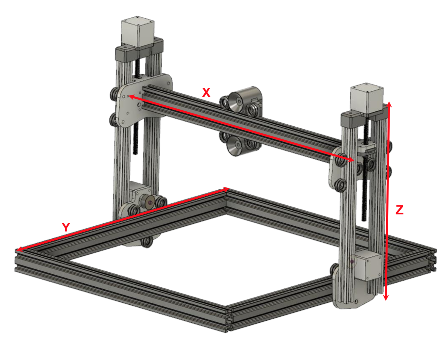
A CAD design assembly, modeled in AutoDesk Fusion 360, depicting the structural framework of the CNC machine, axes labeled. This is assembled primarily using OpenBuilds V-slot extrusions.
Design
The overall design of the frame, seen above, provides a total Z-travel distance of 160mm, and offers good stability by utilizing 2 vertical struts on each side. Each side is also driven by a separate motor, which adds the complication of having to calibrate the motors (via software) so that they run in sync, but also the benefit of added support and assurance that the X axis will rise and fall as desired. These motors are mounted atop each Z axis assembly and each drives a lead screw, which threads through a nut mounted on the Z-axis carriage (below). This is done via an assembly which mounts the nut in somewhat of a “sandwich” configuration. This configuration provides a degree of freedom for the threaded rod, allowing a small amount of movement in the X-axis direction, so that a slight bend in the rod or error in the the motor coupling does not cause movement in the whole machine.
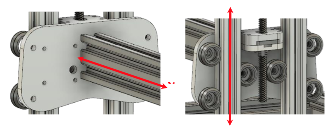
A closeup of the Z carriage assembly. This relies on two vertical shafts to maintain increased stability. The X axis shaft mounts to the plate, as do six V-slot wheels, and the lead screw nut, encased in the assembly through which the threaded rod passes. The nut mounts on the darker plate, which is held on by the portion below it.
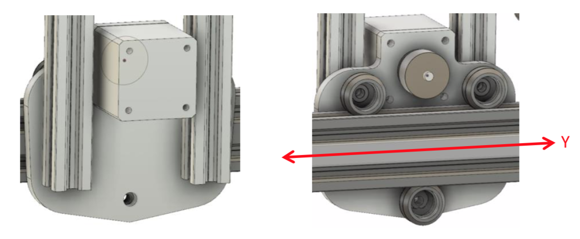
A closeup of the Y carriage assembly. Three V-slot wheels screwed to the plate rest in the V-groove of the extrusion. The Z shafts and the Y-axis motor are also mounted to the plate.
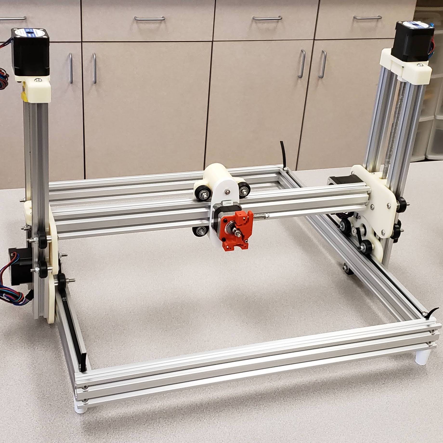
The X and Y axes provide ample travel – over 300mm on the X axis and nearly 400mm for the Y axis. The X axis is driven by another lead screw, which provides great precision and minimizes the complexity of the X-axis carriage (below), as a belt-driven design would require much more complicated geometry. The Y axis, however, is belt-driven. As seen above, each Y-axis motor is mounted to a carriage plate, with a pulley on its shaft. A timing belt runs under the V-wheels and over the pulley, engaging its teeth. The motor, then, can pull itself along the V- slot extrusion. This arrangement is used on both sides of the machine to maintain synchronicity between them. A photograph of the completed assembly is shown on the left.
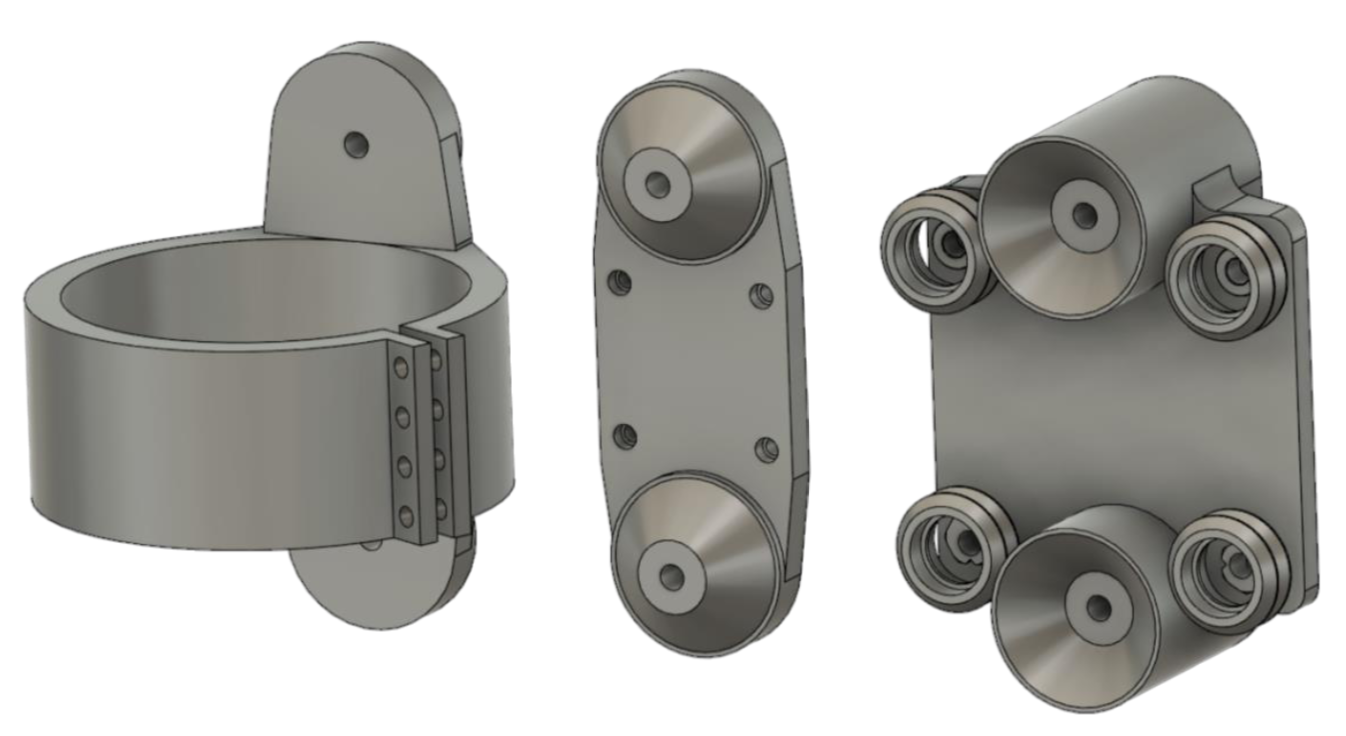
The overall tool-mount design, consisting of a 2-part system - the mount (right), referred to as the X- axis carriage, which receives the tool, and an attachment customized for each tool. The mounting plate (middle) can be used as a starting-off point for any other tool design, such as a mount for a router spindle (left).
Design Process
This project was long and involved, providing many opportunities to utilize what I’ve learned in several courses, particularly those that involved mechanical projects like Dynamics and Kinematics and Design of Mechanical Systems. I began this project by working on a general frame design. I came up with two options, the alternative being unique but less versatile. More details on this alternative can be found in my full report (link above).
Having settled on a frame design and a building material (OpenBuilds V-slot Aluminum extrusions), I directed my attention, before going any further, toward determining whether this idea was even feasible. In my design, the extrusion used for the X-axis is approximately 500mm (about 20in) in length, and will be expected to support a router spindle which, based on online searches, was estimated to weigh approximately 10lbf. Using an estimated torque produced by the weight of the router, I performed a simple finite-element analysis to estimate the displacement due to torsion on a beam of equal length. This estimated that, at worst (at the corners), this torque produces a displacement of under 1mm. I also ran a simulation to estimate the displacement of the beam due to the weight alone, which produced a maximum estimated displacement of only 0.25mm. Again, more details can be found in the full report.
With this confirmation, I was able to continue. Next, I began with work designing a modular tool mounting system. This was definitely one of the more difficult components to design. In total, I had six design ideas, two of which are detailed in the full report. The final contenders were nearly identical, but one features sharp inside corners. Both designs offer the same benefits, but the aforementioned design could not be machined, only 3D printed, due to the sharp inside edges. I wanted this part to be able to be machined out of aluminum, so I elected to adjust the design, the result of which is shown mounted on the .