Reptile Terrarium
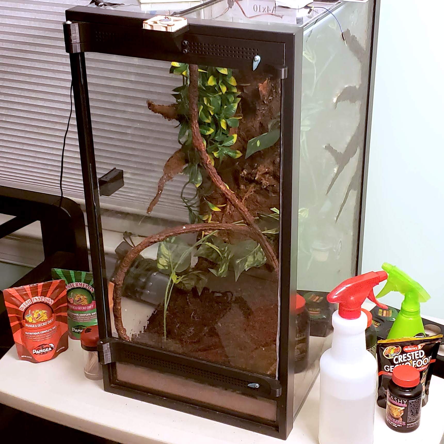
When I was finally ready to get my first arboreal pet reptile I found that front-opening enclosures cost a high premium, leading me to seek a less expensive solution. In the end, without good options available, I made one.
Overview
After a lifetime interested in reptiles and a couple years finally owning some I decided it was time for my first arboreal species, a lizard called a crested gecko. I was disappointed to find, however, that the proper enclosure for such a reptile would cost me at least $100 for even the smallest options, which would still require upgrading over time as the gecko grows. Luckily, there exist conversion kits to turn your regular aquarium into a standing terrarium; however, I felt they were also pricy for what I was getting and my favorite was unavailable for purchase at the time that I needed it. To solve these problems, I decided to design one for myself.
If you’re interested in making use of this design feel free to take a look on Thingiverse
Design Process
For this design I decided on several requirements.
- This should be compatible with standard “20 gallon high” Aqueon-brand aquariums.
- Installation should be fully reversible
- Should not damage the aquarium.
- Should not require any permanent modifications to the aquarium.
- This design should feature a single door which opens to the side and is reasonably easy to open and close.
- The front of the completed terrarium should be primarily glass.
- Non- 3D printed parts should be standard and easily available.
- The design should rely on common 3/32 inch thick glass.
- Only standard sized screws should be needed.
To achieve my goal I would need to design a complete pair of hinges with components that remained stationary on the aquarium and components that attached to the glass used for the door. Due to requirement 2, I couldn’t simply screw something into the aquarium frame or permanently glue it. Because of this, I decided the stationary components would slot into the aquarium frame, which features a convenient lip extending toward the inside of the aquarium.
I started by taking measurements of the aquarium frame and sketching it out, since this is what my hinge will have to fit around.
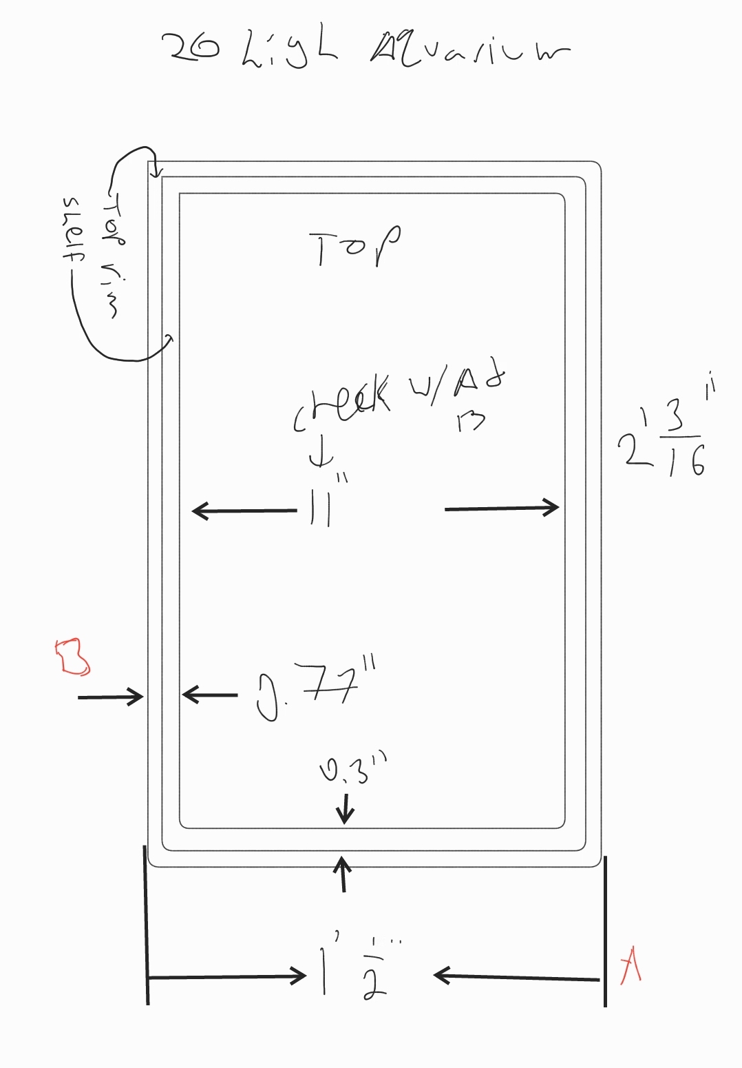
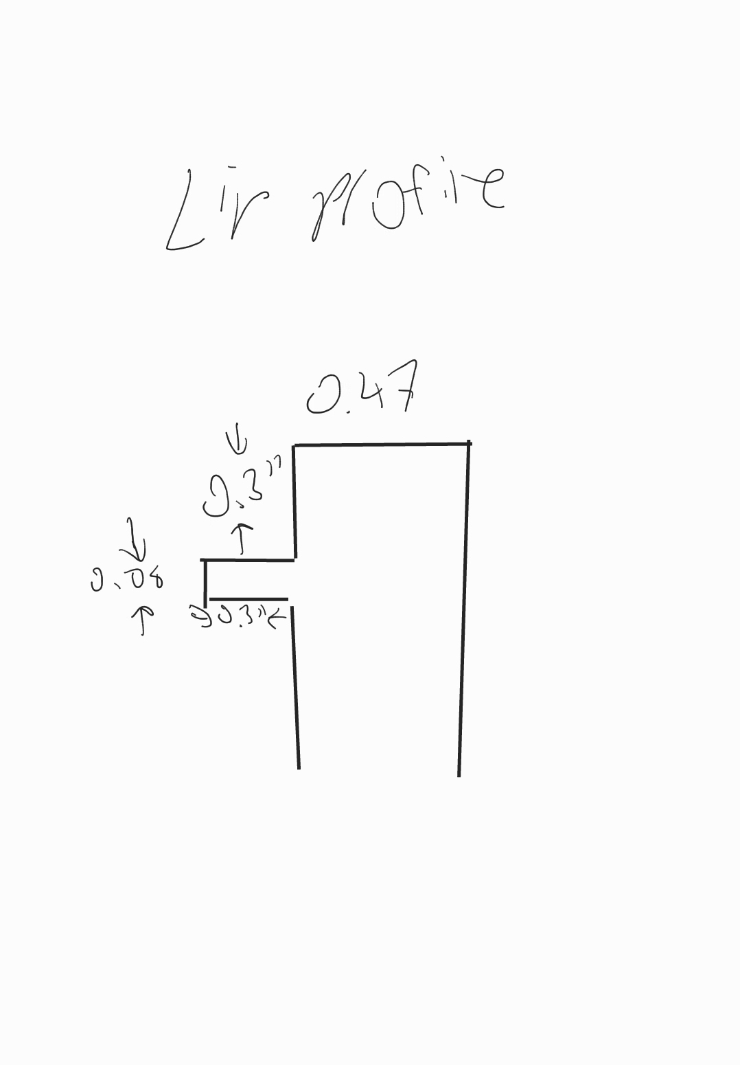
My dimensioned sketch of the aquarium frame to make clear the dimensional relationships between the components.
This design required a fair amount of measurement and testing for fit. A loose fit would leave the hinges I was designing insecure, and a fit that’s too tight might put enough strain on the glass to cause a crack. So my first step was to calibrate the weakest dimension, that being between the two long edges of the aquarium. I created a simple slotted beam (shown below) that I could slot onto the aquarium frame like I intended to do with the final product. This would allow me to check my accuracy for the innermost dimension of the frame (the thin lip that goes inside the perimeter. 11” above), the “outer” dimension of the frame (the inner portion of the rim of the aquarium. Would be 11.6” according to the sketch), and the depth measurement to the lip (0.3”).
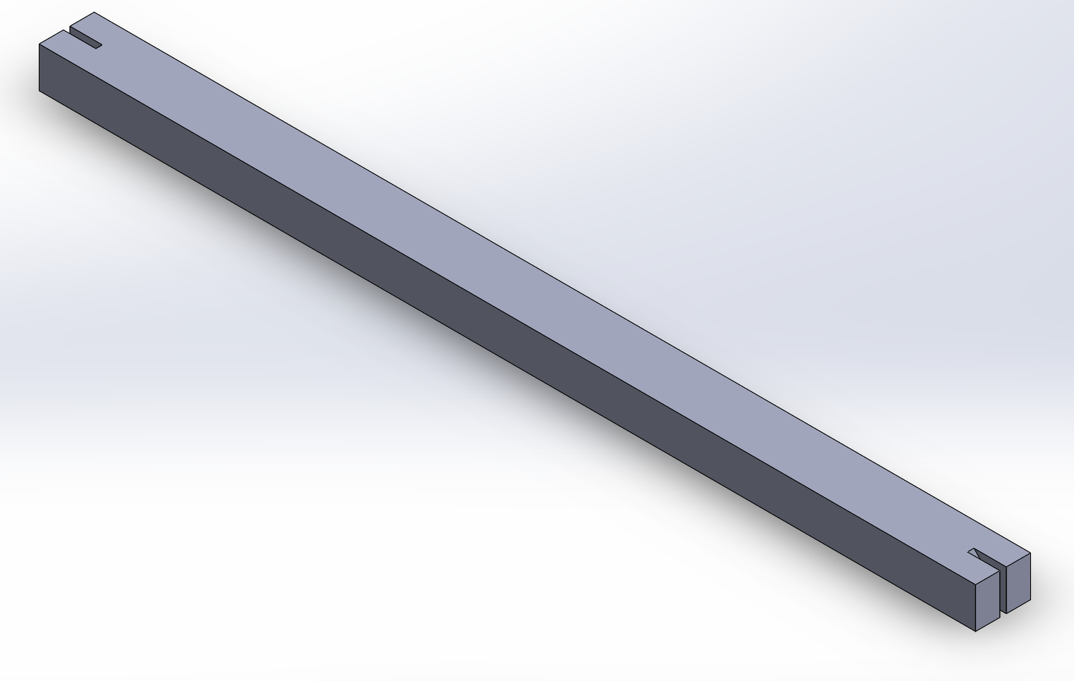
A quick and simple beam with slots on the ends to test my aquarium frame dimensions.
This part was a pretty good fit, though a little snug along the “outer” dimension as defined above. The appropriate adjustment was made and I moved on to designing a proper hinge, my first iteration shown below. This, I was aware, was an incomplete design lacking vent holes and a latching mechanism; however, it was enough to test. With the knowledge that I did not intend to actually use this part, I only 3D printed the top portion of it, slicing off as much as I could from the bottom while maintaining structural integrity.
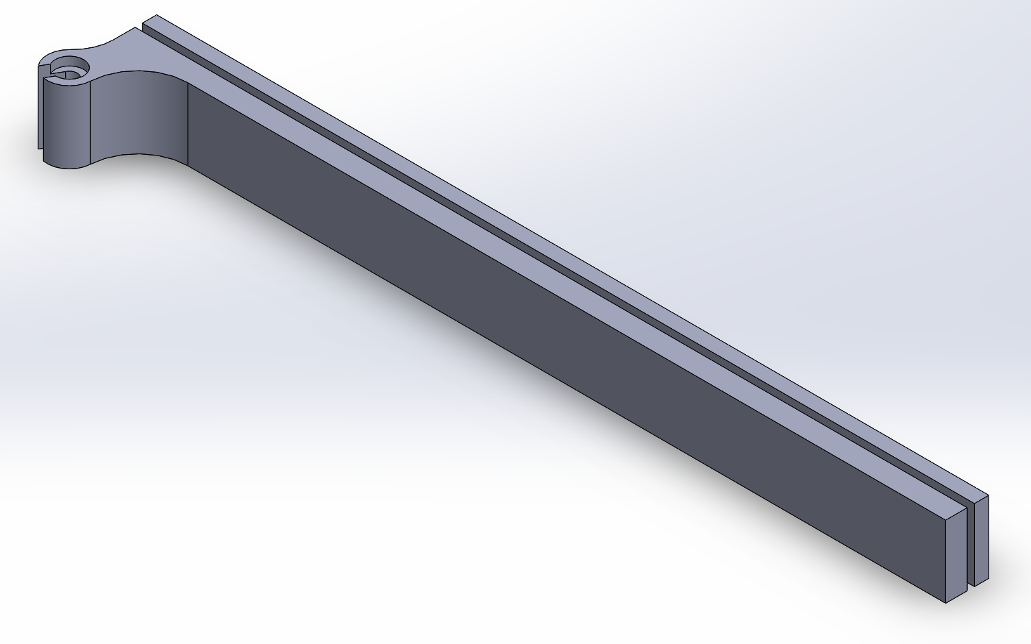
Version 1 of the stationary portion of the hinge.
Once again, this part was a fairly good fit, but it did reveal a problem I hadn’t noticed previously. The aquarium is sealed together with silicone, with fairly large blobs in the corners. The installation technique is to insert the part at and angle somewhere near the middle of the aquarium, align the slots on the short ends, and rotate the part in place before sliding it up or down to its final position. I found that the silicone blobs got in the way of the hinge as I tried to slide it into place at the top. But otherwise, it fit great. So, with this in mind, I was ready to try to finalize the design.
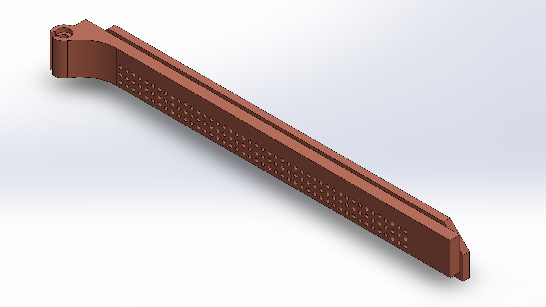
Version 2 of the stationary portion of the hinge.
In the final hinge shown above I added deep chamfers in the back corners to accommodate the silicone, along with an array of vent holes, which can also accept M3 screws (albeit, snugly). In addition, I added a lip on the bottom as a backstop for the door, which I designed in parallel with this final version of the stationary component, and which I will now discuss.
Below you will find a CAD model of the door-side component of the hinge. As pictured, this would be part of the bottom hinge.
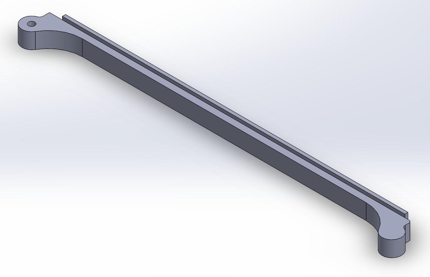
The door-side component of the bottom hinge.
I designed this at the same time that I was designing the final version of the stationary portion of the hinge, meaning that I could use that model for the critical dimensions and ensuring compatibility between the models and with the aquarium, as I had already tested the fit of the stationary component. This features a slot to accommodate standard 3/32 inch thick glass and rests on the lip of the aquarium frame as well as a lip designed into the stationary part of the hinge. This prevents any larger gaps that a small critter might be able to squeeze out of, even in spite of small errors in the print or installation.
Accessories
I designed two additional components for this design: a duct to direct air in or out of the enclosure, and a latch to hold the door shut. I won’t go into the latch here being that it’s such a simple component but I’ll briefly go over the duct design.
I quickly found that humidity in the enclosure did not readily escape in spite of the numerous vent holes. This is a problem for the crested gecko I intended to house in it, which lives in a wet environment that should be able to dry out during the day. I designed this simple duct to allow me to force air through the enclosure. It features four screw holes aligned with the vent holes and an opening large enough for air to pass through 9 of these holes. I found the most effective arrangement was to set the fan so that it pulls air from the enclosure and to mount this at the top of the enclosure. Finally, I designed this to be compatible with standard 40mm fans, commonly used with 3D printers and other simple electronics.
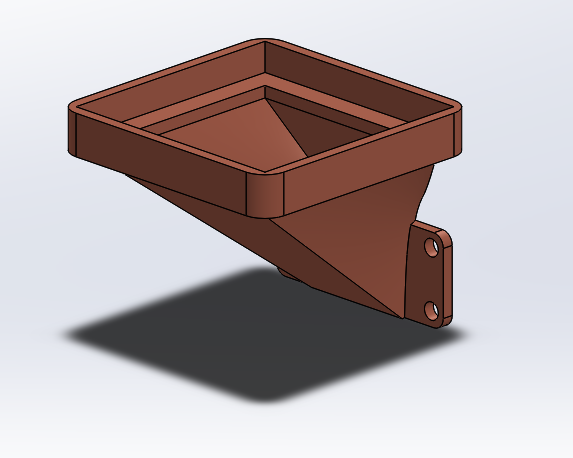
A ventilation duct to force air through the enclosure. Compatible with 40mm fans.