Ladder Climber
The course Dynamics and Kinematics concluded with a project for which we were asked to design and construct a machine that will climb a ladder, the 'ladder' being a long wire shelf. Working in a team of 3, we ended up being the only team with a machine that could successfully climb the full length of the ladder.
Overview
For this project, teams of 3 were tasked with developing a machine capable of climbing a “ladder” constructed from a wire shelf propped vertically. The design for this climber was required to be centered around the use of a 4-bar linkage, and was to be constructed from 0.25in thick crafting plywood and assembled using clevis fasteners. Bushings of various materials were available to build hinges into the construction and reduce cost, as they are much less expensive than ball bearings. My team made use of the Robert’s mechanism, a 4-bar linkage that provides linear motion. We used a 2-platform design with weighted hooks which automatically deploy, keeping the machine hooked to the wires that form the ladder. In the end, our machine performed smoothly and very effectively, remaining extremely stable throughout its full ascent.
Design
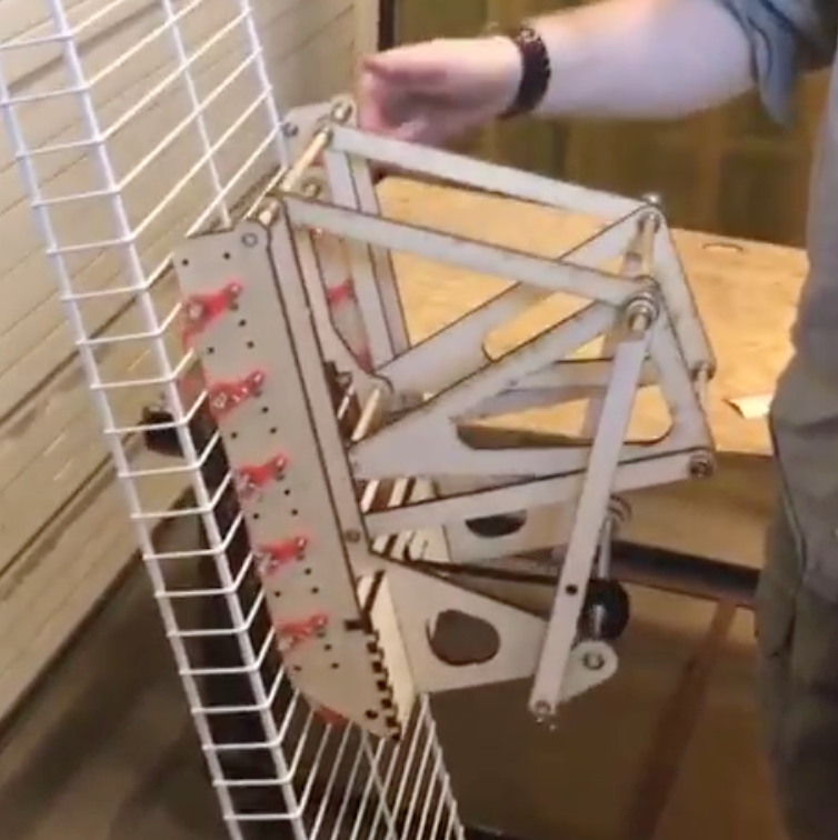
The main mechanism in this design is the Robert’s linkage, a four-bar linkage that produces linear motion. A demonstration of the linkage can be seen in the video below. The full climber design can be imagined as consisting of 2 platforms, a main platform and a sliding platform. Each platform features 2 rows of 5 hooks, spaced such that all of them engage the ladder together. As the platforms move in relation to one another, one remains hooked to the ladder while the other reaches upward. The guides used for the sliding mechanics (orange in the CAD model below) are made from acrylic to minimize friction, and are sandwiched between ball bearings to keep them on track. The hooks (black) are also made of acrylic to ensure they slide smoothly on the surface of the ladder when they retract during ascent. The rounded protrusion on the hooks with the small hole are used to weight the hooks for consistent deployment. Small M3 screws were threaded into the small holes for this purpose. A single gearmotor drives the mechanism via belt and pulley (grey). This drive shaft was made from aluminum to maximize torsion resistance with little addition of weight, and was epoxied to the input members of both the left and right Robert’s linkages that form the framework of the machine.
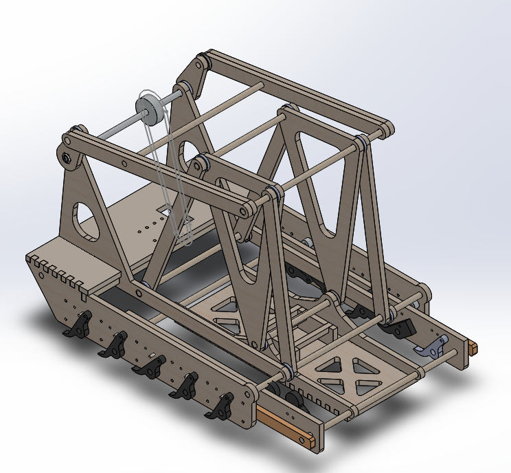
A CAD design assembly, modeled in SolidWorks, depicting the full construction of the ladder climber.
Performance
Below is a video demonstrating the machine’s performance. In the end, of seven total designs, this was the only capable of ascending the full length of the ladder (as shown in the video). The excess of hooks kept the machine well secured to the ladder, with no sign of any problems. The hooks deployed consistently, and the platform sliders performed smoothly. The greatest problem with this design was weight, this being a very relatively heavy machine. We saw this problem in powering the machine, as it grew sluggish after only approximately 10 minutes.