Mini Golf Robot
Download full project report here
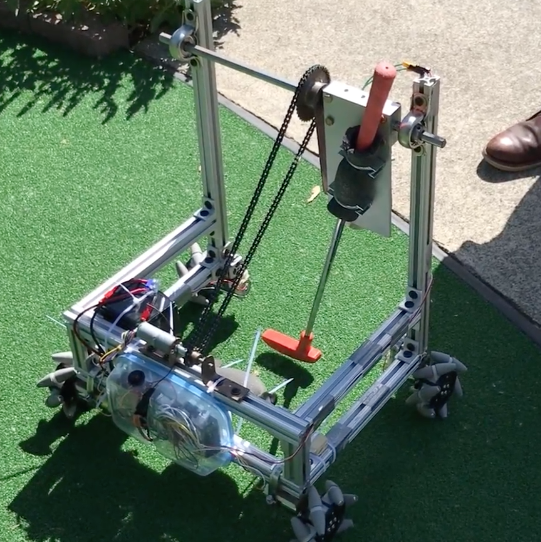
For the course Design of Mechanical Systems, we were tasked with designing and constructing a robot to be used in a mini-golf competition against the professor's 6-year-old daughter. I led the group responsible for the driving subsystem.
Overview
For this project, teams of 8 were asked to design and build a robot capable of playing a hole of mini-golf through from start to finish. This means that in addition to being able to physically strike the ball, the machine also needs to be able to move to reposition itself for each shot, without being touched by team members. In addition, the robot was required to use one of the putters available at the course without damaging it, the robot mustn’t damage the green while getting in position, and three minutes were allotted to finish each hole. We were given 10 weeks to complete this design and assembly, after which time the robot would be put head-to-head against the professor’s 6-year-old daughter. Members of the project team were organized into two groups, one of which focused on developing the driving subsystem, and the other focused on developing the putting subsystem. A team leader was assigned to lead the project, and a group leader was assigned within each group to lead the development of their respective subsystems. I led the group responsible for developing the driving subsystem.
Design
The design consists of two subsystems: a driving subsystem, and a putting subsystem. To meet our goals, we required that the driving subsystem be capable of omnidirectional translation and rotation to maximize mobility and simplify the process of lining up a shot. The putting subsystem should be capable of controlledly swinging the equipped putter in a manner similar to a golfer driving a putt.
In the end, we chose to construct the robot chassis out of 80/20 extrusions. This frame consisted of a simple box below and two tall vertical struts used for the putter assembly. More detail can be seen in the CAD assembly shown below. On the vertical struts were mounted 2 ball bearings, which allowed a rod running between the two to rotate freely. On the rod was mounted a sprocket, a plate on which the putter could be mounted using 2 U-bolts, and a plate which held a large electromagnet. The plate on which the putter was mounted and that which held the electromagnet were decoupled and each could swing independently of the other. In order to putt, the magnet is enabled and sticks to the putter plate, a motor engages a chain which engages the sprocket, and raises the magnet plate which raises the putter plate with it. When the shot is ready, the magnet is disengaged and the putter swings freely under gravity.
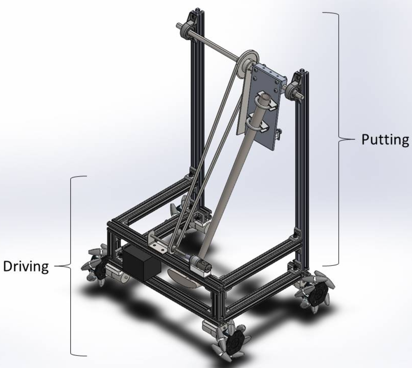
A completed CAD depicting the robot's final design.
The driving system was constructed simply. My group designed custom motor mounts (shown below), designed to securely mount on 80/20 extrusion, while also keeping the motor well supported. These were mounted on the bottom of the chassis, and wheels were mounted directly on the motor shafts. After selecting our wheels (more details below) and designing the aforementioned motor mounts, the major challenge was controlling the robot and driving the motors.
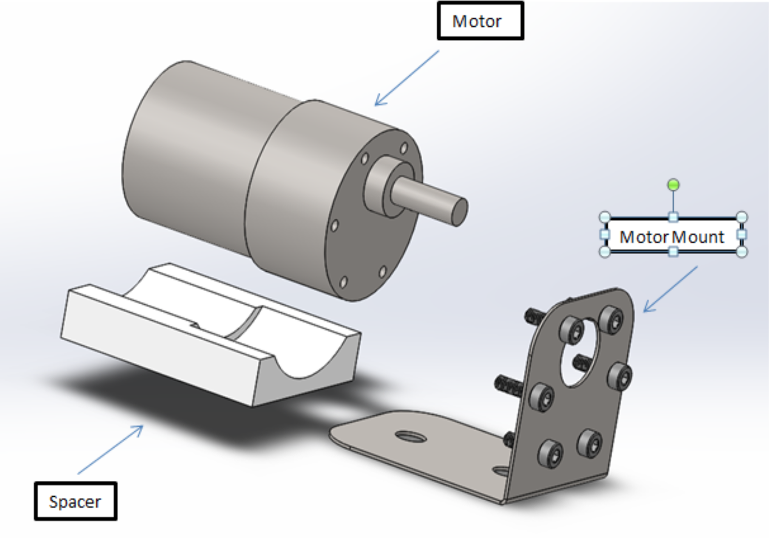
Shown here is the motor mount assembly. This orientation will be flipped when fully assembled (so that the bent metal bracket is mounted to the underside of the robot), and the motor will be strapped against the spacer using hose clamps (not shown).
The Driving System
Leading the team developing the driving system, I first held a brainstorming meeting. We sought a method of omnidirectional locomotion that also allowed the robot to pivot on the spot. This could be achieved if all wheels were powered and had motorized swivels; however, this would require twice as many motors as wheels and overcomplicated the system, so we continued searching for simpler solutions. Through research, we discovered “omniwheels,” wheels with rollers along their perimeter, which, if mounted 90 degrees from one-another, would allow the robot to move in any direction. The downside of this was that the force output from the wheels on the ground would be greatly decreased for every direction except the diagonals. Upon further research, a teammate discovered “mecanum wheels,” which are mounted like standard wheels and have rollers along the perimeter at a 45 degree angle, as shown in the image below. These, like omniwheels, can provide omnidirectional locomotion (following rules outlined in a graphic below), but they have an advantage over omniwheels in that there is little to no reduction in force applied to the ground in the forward and reverse directions.
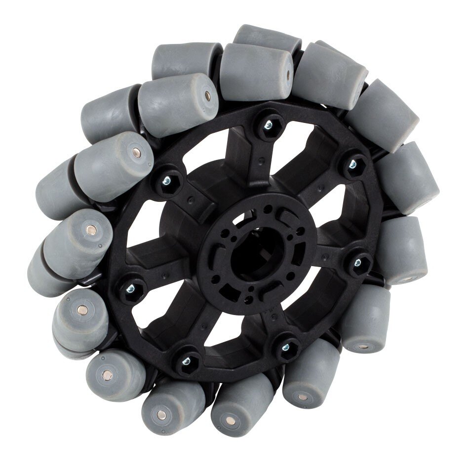
An example of a mecanum wheel sold by VEX Robotics. Notice the grey rollers mounted 45 degrees from the axis of rotation.
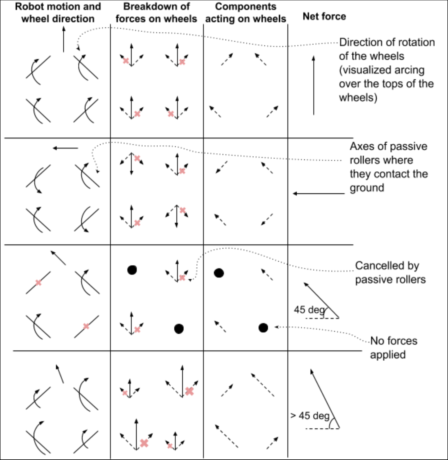
A breakdown of the forces acting on mecanum wheels to produce various movements.
We elected to purchase unassembled AndyMark 4in diameter wheel kits for cost savings and ease-of-use, as they required only simple, inexpensive blocks to mount them directly to a motor shaft. We selected our motors based on the estimated torque required to drive the robot up a 30 degree incline. In our design, each wheel is driven directly by its own motor, each of which are driven by an arduino via SparkFun motor drivers.
Now, we needed some way to control the robot. Being the only member of the team comfortable with electronics or coding, this is where I placed most of my effort. We were provided with a high-end radio controller and receiver. The receiver, powered with 5V from an Arduino board, has a separate output pin for each radio channel. These outputs are digital, meaning that they will be read by the board as having a value of 1 if it is high (meaning there is a voltage on that pin) or a 0 if it is low. These outputs pulse on and off at various frequencies depending on the state of the control. For example, channel 2 (as seen in the figure below), which controls rotation of the robot, will pulse least rapidly when the stick is pushed farthest left, and most rapidly when the stick is pushed farthest right. The Arduino reads these signals and calculates the time passed between pulses in microseconds. This ranges from approximately 1080 to approximately 1880 where, in the example of channel 2, 1080 microseconds are measured between pulses when the stick is in the far right position, and 1880 microseconds when the stick is in the far left position. The motor drivers accept inputs ranging from -255 (which generates a full 12V running the motor backward) to +255 (12V running the motor forward), so an equation was derived to scale the pulse readings to be within that range, where a pulse reading of 1080 will result in a value of -255 when passed through the equation and 1880 will produce +255.
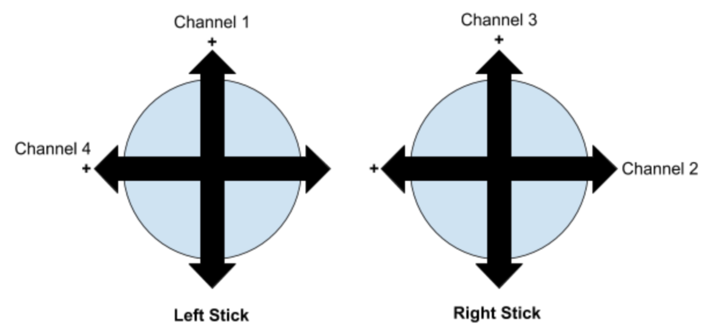
A diagram of the RC joystick controls and their corresponding channels. The “+” indicates the direction in which the pulse width from the receiver increases.
The putting controls are similar, with channel 3 controlling the rise and fall of the putter to power the swing; however, there are two distinct differences. First is the trigger mechanism. This will depend on an electromagnet controlled with channel 5 (not shown), which is linked to a switch on the radio controller. When the switch is in the up position (producing a pulse width of approximately 1880 microseconds), a PWM input of 255 will be supplied to the motor driver, which should trigger an output of 12V to the magnet, enabling it. As soon as the switch is flipped (producing a new pulse width of approximately 1490 microseconds), an input of zero will be supplied to the motor driver, the magnet will be disabled and the putter will be allowed to swing freely.
The second distinct difference in the implementation of the putter system is the way in which the position of the putter is maintained in preparation of a swing. The gearmotor we selected to raise the putter does not lock up, so backdriving is a considerable concern when the putter is in its raised position. To mitigate this issue, a gearmotor was selected with a rotary encoder attached, which can provide position information for the motor shaft. The construction and functionality of this encoder is discussed in detail in the full report available for download. The radio controller is used to bring the putter to the desired angle and then the Arduino watches the encoder to determine whether the putter has moved. If the encoder indicates that the putter has lowered, the Arduino will send power to the motor to raise the putter back to the desired position. This was implemented using proportional control, meaning that the power supplied to the motor is directly proportional to the encoder position’s distance from the desired position. Though this does have the downside that there will always be some amount of “sag” in the putter (ie. it will always sink some amount), this ensures that the an equilibrium will be found where the motor provides exactly the torque required to counter the torque applied to the shaft by the putter.